
1.Introduction
The threads you see every day without much thought come in various types depending on where they are used, their purpose, and the materials they are made from. This time, we’ll explain about metal threads that are commonly machined through cutting processes.
2.Types of Threads
Threads can be broadly classified into two types:
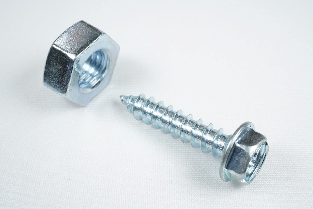
- External Threads: Cut on the outside (bolts etc…)
- Internal Threads: Cut on the inside (nuts etc…).
While all screws are threaded, you can distinguish them by whether the threads are on the outside or inside diameter. Screws have helical, triangular-shaped grooves, and the spacing between these grooves is called the “pitch”. Though they may all look similar, threads are categorized into many types, such as Metric Threads, Parallel Pipe Threads, Taper Pipe Threads, Unified Threads, Whitworth Threads, and Trapezoidal Threads.
The size of a thread is referred to as the “Nominal Diameter”, and it is represented by a numerical value following the symbol that indicates the thread type. For example, in the case of a metric thread, it might be represented as M30×P1.5. This means that for a metric thread, the thread angle is 60°, the thread’s outer diameter is φ30, and the pitch is 1.5mm. For a tapered pipe thread, it might be represented as Rc1/2, which indicates a taper angle of 1.7899°, a thread angle of 55°, a pitch of 14 threads per inch (equivalent to 1.8143), and a nominal diameter of 1/2 inch.
As you can see, there are many types of screws, and the appropriate screw shape is selected based on its intended use.
3.Basic Concepts of Thread Cutting
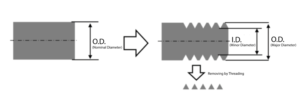
External Threads
The external diameter of the thread is cut to the major diameter. Then, a threading tool is used to cut the minor diameter. In case of turning, the thread is cut in several passes with appropriate depth increments to complete the process. Threads can be cut using rolling rollers, dies, or planetary taps.
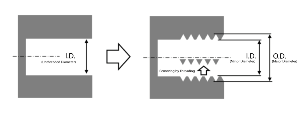
Internal Threads
The internal diameter is cut to the minor diameter. Then, an internal threading tool is used to cut to the major diameter. Like external threading, the thread is cut in several passes with appropriate depth increments. Tapping is commonly used for internal threads of small diameters.
Since external threading is cut on the surface, the process is visible. However, internal threading is performed inside the material, which make it difficult to see and handle chips, thus increasing the difficulty compared to external threading.
Notes on Processing
When machining external and internal threads, there are a few important points to keep in mind. For external threads, you typically start with a material that has been finished to the nominal diameter of the thread. However, for internal threads, you need to machine the material to the diameter known as the “minor diameter” or “thread Unthreaded diameter” before cutting the threads. For example, for an M30×P1.5 thread, the external diameter should be φ30, while the minor diameter of the internal thread should be φ28.37. Mistakenly machining the internal diameter to the nominal diameter φ30 will result in no thread formation.
4.What is a “Wiper”
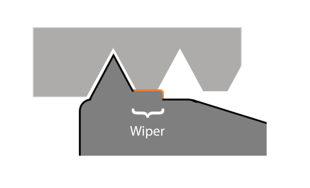
A wiper is a side cutting edge of a threading insert designed to trim the thread crests and improve the surface finish of the threads. While the main cutting edge forms the thread, the wiper edge smooths the thread crest as it cuts. This wiper edge helps remove sharp corners at the thread crests, reducing burr formation and creating a smoother, rounded crest. Additionally, it contributes to increasing the strength of the screw itself.
A thread insert with wiper is designed for specific thread pitches and cannot be used interchangeably for different pitches. They offer the benefit of producing burr-free, smooth threads, but require particular inserts for each pitch, presenting both advantages and disadvantages.
Threading Insert with Wiper
- Produces burr-free, smooth threads with rounded crests, enhancing thread strength.
- Requires a dedicated tool for each pitch.
Threading Insert without Wiper
If the thread angle is the same, a single insert can be used for various pitches. However, burrs are likely to form at the thread crest, which may require additional finishing or deburring processes. When machining without the wiper edge, the minor diameter can be made slightly larger or smaller before cutting the thread to intentionally create a flat surface at the thread crest. Shaping it into a trapezoid can reduce burrs and enhance the strength of the thread.
5.Choose the Appropriate “Cutting Method (infeed)” for the Intended Purpose.
When machining threads on a CNC lathe, there are mainly three types of cutting methods. Each method has its own characteristics, and the infeed method provides different threading cycles. The choice of cutting method is adjusted according to the machining conditions.
A threading cycle is a sequence that organizes a series of operations for thread machining, making it easier to create programs. It commands four actions—positioning the cut, threading, retreating, and returning—using a single line of code in the program
Radial Infeed (Straight Infeed) – G92
This is the most common and simplest cutting method, often considered the standard for thread machining on CNC lathes. It starts cutting from the center of the groove being machined. As the groove deepens, the contact area of the cutting-edge increases, leading to higher cutting resistance. Consequently, screws with larger pitches (taller thread heights) are more prone to chatter.

Flank Infeed (Single Flank Infeed) – G76
This cutting method involves machining along one side of the groove. It allows for a uniform cutting cross-section and is chosen for large pitch thread (with higher thread heights) or when chatter occurs during radial infeed machining. Due to its single edge cutting, it features lower cutting resistance and relatively good chip removal.

Alternate Infeed (Staggered Cutting)
This cutting method combines radial infeed and flank infeed techniques. It involves cutting alternately from the center of the groove to the left and right. Due to its single-edge cutting, it is mainly used for machining large-pitch threads. It can be challenging to program and requires adjustments to the program for modifications to the cutting process.

6.Example Programs for Thread Cutting
In actual threading programs for CNC lathes, threading cycles such as G92 and G76 are primarily used.
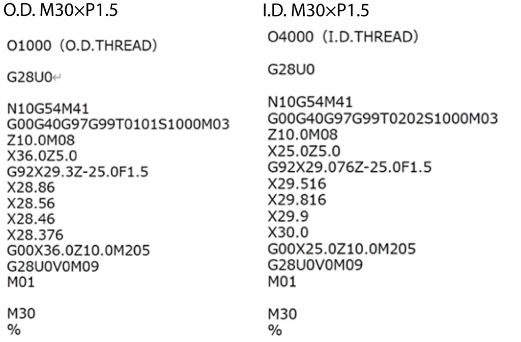
Radial Infeed (Straight Infeed) – G92 Cycle
G92 X (Thread Major Diameter) Z (Thread End) F(Pitch) R (Radius Difference)
Threading operations involve several incremental cuts to gradually machine the thread, finishing with the thread major diameter. Adjusting the thread major diameter during the threading cycle is sufficient, as other operations will continue as programmed. If the R parameter is omitted, a straight thread will be produced.
Example of Program
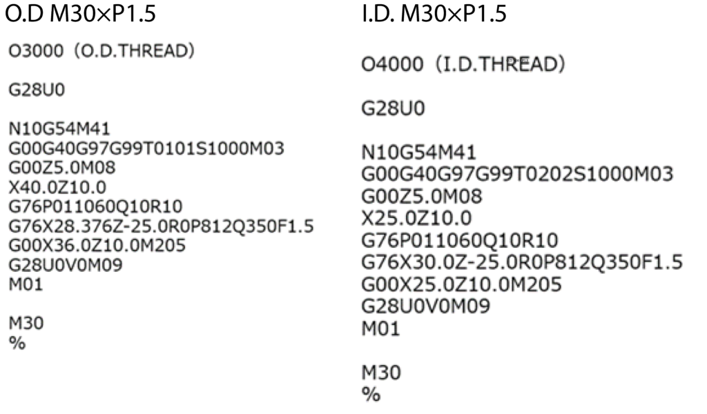
Flank Infeed (Single Flank Infeed) – G76 Cycle
G76 P(Final Finishing Passes) (Chamfering distance) (Thread Angle) Q(Minimum Cutting Depth) R(Finishing Allowance)
G76 X(Thread Major Diameter) Z(Thread End) R(Radius Difference) P(Thread Height) Q(Initial Cutting Depth) F(Pitch)
The flank infeed cycle is a two-line thread machining cycle. It must be commanded with two lines, and the G-code on the second line cannot be omitted. If the R parameter is omitted, a straight thread will be produced.
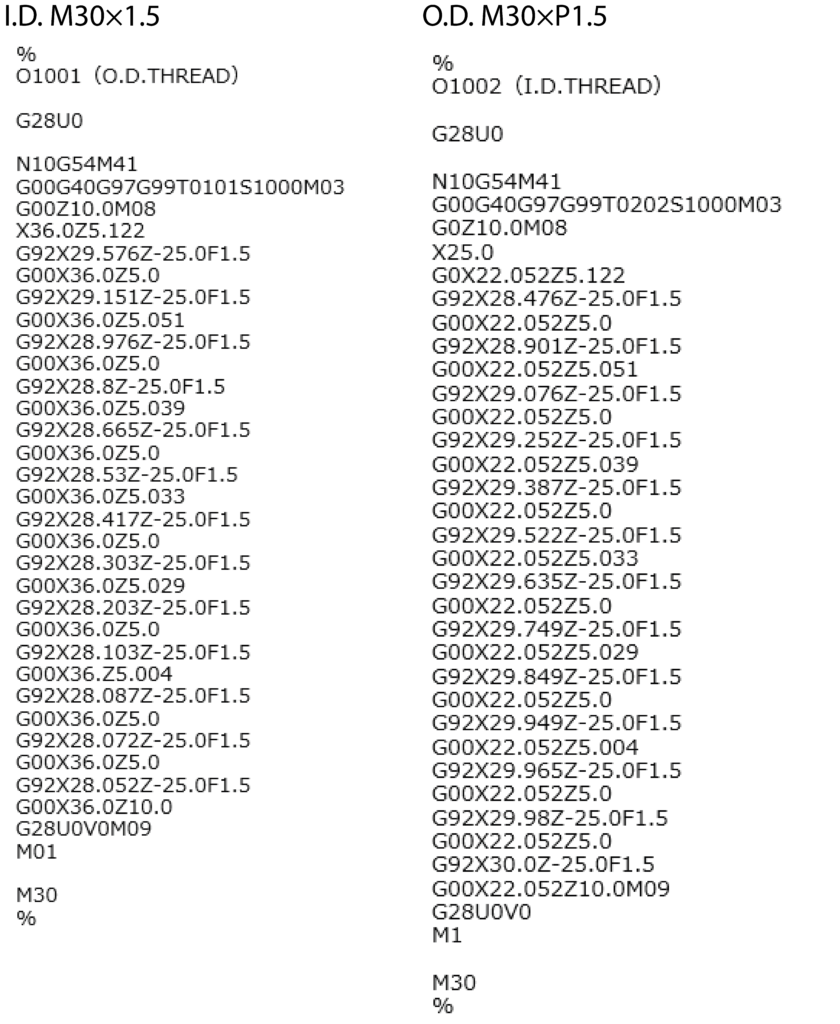
Alternate Infeed (Staggered Cutting)
Alternate infeed, also known as staggered cutting, is a machining method that alternately processes the screw thread from left to right. Since it cannot be handled by a standard thread machining cycle, radial infeed machining is performed while changing the start point. Calculating the start point for screw machining can be tedious, so programs are created using CAM or conversational programming.
7.Summary
This time, we explained the types and programming methods for threading on a CNC lathe. If you’ve only tried one type of infeed method before or have been struggling with chatter, why not try the infeed methods introduced this time? We’ve also included a sample program, so we hope you find it helpful.
One more Thing
[Advertorial] Introduction to “Oscillation Threading”
At Nakamura-Tome, we offer a unique chip-braking function called “Oscillation Threading.”
This function is practical for breaking long chips into small fragments using oscillation motions during thread cutting.
Contact Nakamura-Tome
Nakamura-Tome welcomes inquiries not only about the Oscillation Threading but also about our products and machining inquiries.
Please feel free to contact us via the link below.
